
A look at the different linear motors available and how to select the optimal type for your application.
The following article is an overview of the different types of linear motors available, including their principles of operation, history of development of permanent magnets, design methods for linear motors and industrial sectors using each type of linear motor.
Linear Motor Technology can be: Linear Induction Motors (LIM) or Permanent Magnet Linear Synchronous Motors (PMLSM). PMLSM can be iron core or ironless. All motors are available in flat or tubular configuration. Hiwin has been at the forefront of linear motor design and manufacturing for 20 years.
Advantages of Linear Motors
A linear motor is used to provide linear motion, i.e., moving a given payload at a dictated acceleration, speed, travel distance and accuracy. All motion technologies other than linear motor driven are some sort of mechanical drive to convert rotary motion into linear motion. Such motion systems are driven by ball screws, belts or rack and pinion. The service life of all these drives is highly dependent upon the wear of the mechanical components used to convert rotary motion into linear motion and is relatively short.
The main advantage of linear motors is to provide linear motion without any mechanical system because air is the transmission medium, therefore linear motors are essentially frictionless drives, providing theoretically unlimited service life. Because no mechanical parts are used to produce linear motion, very high accelerations are speeds are possible where other drives such as ball screws, belts or rack and pinion will encounter serious limitations.
Linear Induction Motors
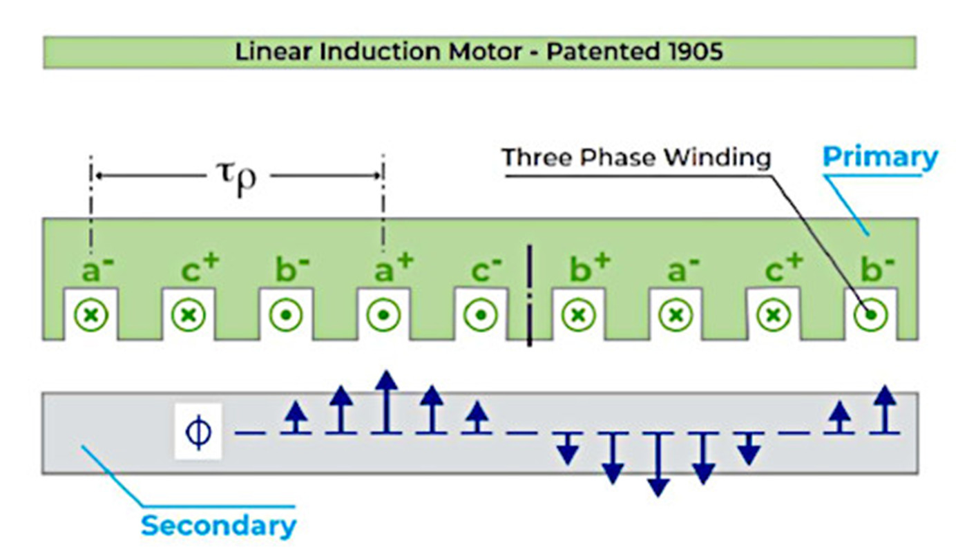
Fig 1
The linear induction motor (LIM) was the first invented (US patent 782312 – Alfred Zehden in 1905). It consists of a “primary” composed of a stack of electrical steel laminations and a plurality of copper coils supplied by a three-phase voltage and a “secondary” generally composed of a steel plate and a copper or aluminum plate.
When the primary coils are energized the secondary becomes magnetized and a field of eddy currents is formed in the secondary conductor. This secondary field will then interact with the primary back EMF to generate force. Direction of motion will follow Fleming’s left-hand rule i.e.; the direction of motion will be perpendicular to direction of current and direction of field / flux.

Fig 2
Linear induction motors offer the advantage of very low cost because the secondary does not use any permanent magnets. NdFeB and SmCo permanent magnets are very expensive. Linear induction motors use very common materials, (steel, aluminum, copper), for their secondary and eliminate this risk of supply.
However, the downside of using linear induction motors is the availability of drives for such motors. While it is very easy to find drives for permanent magnet linear motors, it is very difficult finding drives for linear induction motors.
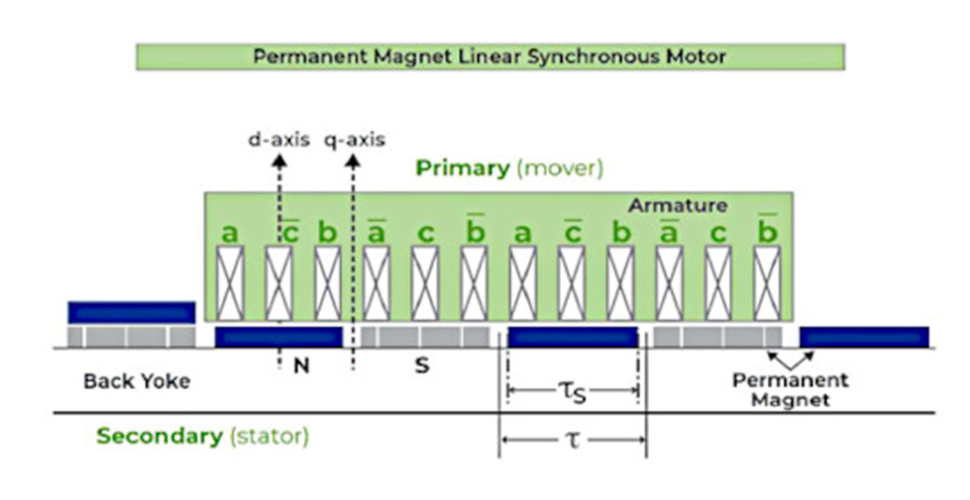
Fig 3
Permanent Magnet Linear Synchronous Motors
Permanent magnet linear synchronous motors (PMLSM) have essentially the same primary as linear induction motors (i.e., a set of coils mounted on a stack of electrical steel laminations and driven by a three-phase voltage). The secondary differs.
Instead of a plate of aluminum or copper mounted on a plate of steel, the secondary is composed of permanent magnets mounted on a plate of steel. Each magnet’s direction of magnetization will alternate with respect to the previous one as shown in Fig. 3.
The obvious advantage of using permanent magnets is to create a permanent field in the secondary. We have seen that force is generated on an induction motor by the interaction of the primary field and the secondary field which is only available after a field of eddy currents has been created in the secondary through the motor airgap. This will result in a delay called “slip” and a motion of the secondary not in synch with the primary voltage supplied to the primary.
For this reason, induction linear motors are called “asynchronous”. On a permanent magnet linear motor, the secondary motion will always be in synch with the primary voltage because secondary field is always available and without any delay. For this reason, permanent linear motors are called “synchronous”.
Different types of permanent magnets can be used on a PMLSM. Over the last 120 years, the ratio of each material has changed. As of today, PMLSMs are using either NdFeB magnets or SmCo magnets but the vast majority are using NdFeB magnets. Fig. 4 shows the history of Permanent magnet development.
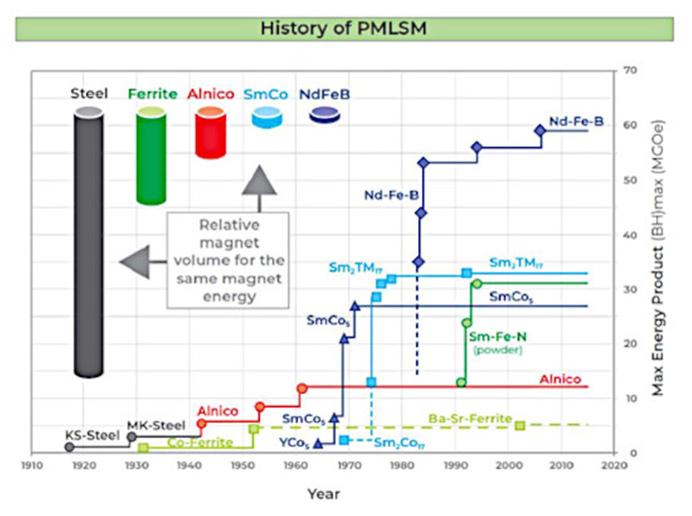
Fig 4
Magnet strength is characterized by its energy product in Megagauss-Oersteds, (MGOe). Until the mid-eighties only Steel, Ferrite and Alnico were available and delivering very low energy products. SmCo magnets were developed in the early 1960’s based on work by Karl Strnat and Alden Ray and later commercialized in the late sixties.
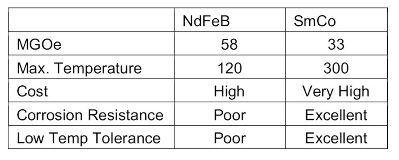
Fig 5
The energy product of SmCo magnets was initially more than double of the energy product of Alnico magnets. In 1984 General Motors and Sumitomo independently developed NdFeB magnets, a compound of Neodynium, Iron and Boron. A comparison of SmCo and NdFeB magnets is shown in Fig. 5.
NdFeB magnets develop much higher force than SmCo magnets but are much more sensitive to high temperatures. SmCo magnets are also much more resistant to corrosion and low temperatures but are more expensive. When the operating temperature reaches the magnet’s maximum temperature the magnet starts to demagnetize, and this demagnetization is irreversible. The magnet losing magnetization will cause the motor to lose force and be unable to meet the specs. If the magnet operates below maximum temperature 100% of the time, its strength will be preserved almost indefinitely.
Because of the higher cost of SmCo magnets, NdFeB magnets are the right choice for most motors, particularly given the higher force available. However, for some applications where operating temperature can be very high it is preferable to use SmCo magnets to stay away from maximum operating temperature.
Design of Linear motors
A linear motor is generally designed via Finite Element Electromagnetic Simulation. A 3D model will be created to represent the lamination stack, coils, magnets, and steel plate supporting the magnets. Air will be modeled around the motor as well as in the airgap. Then materials properties will be entered for all components: magnets, electrical steel, steel, coils, and air. A mesh will be then created using H or P elements and the model solved. Then the current is applied to each coil in the model.
Fig. 6 shows the output of a simulation where flux in tesla is displayed. The main output value of interest for the simulation is of course Motor force and will be available. Because the end turns of the coils do not produce any force, it is also possible to run a 2D simulation by using a 2D model (DXF or other format) of the motor including laminations, magnets, and steel plate supporting the magnets. The output of such a 2D simulation will be very close to the 3D simulation and accurate enough to assess motor force.
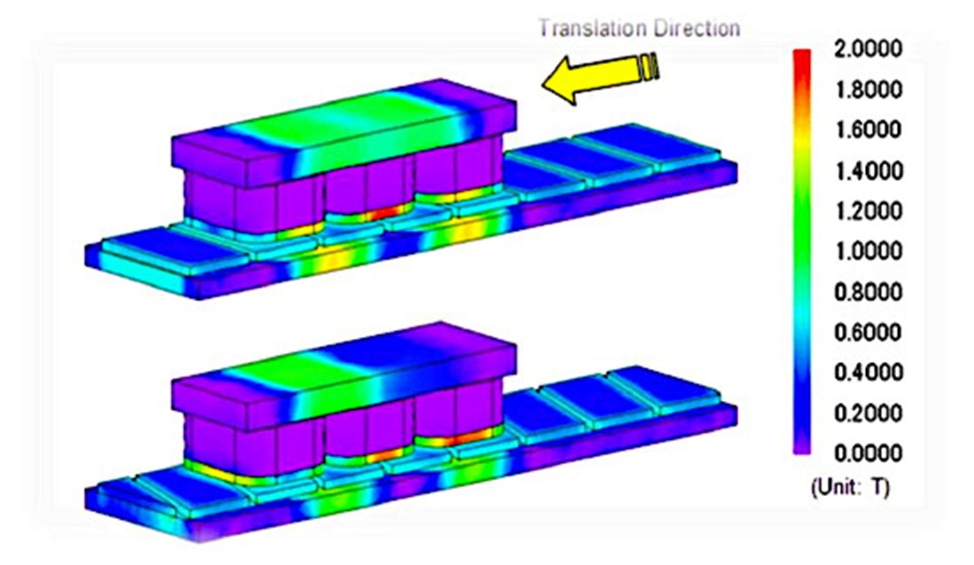
Fig 6
A linear induction motor will be modeled the same way, either via a 3D or 2D model but the solving will be more complicated than for a PMLSM. This is because the magnetic flux of the PMLSM secondary will be modeled instantly after entering the magnets properties, therefore only one solve will be required to obtain all output values including motor force.
However, the secondary flux of the induction motor will require a transient analysis (meaning several solves at a given time interval) so that the magnetic flux of the LIM secondary can be built and only then the force can be obtained. The software used for the Electromagnetic Finite Element Simulation will need to have the ability to run a transient analysis.
Linear Motor Stage
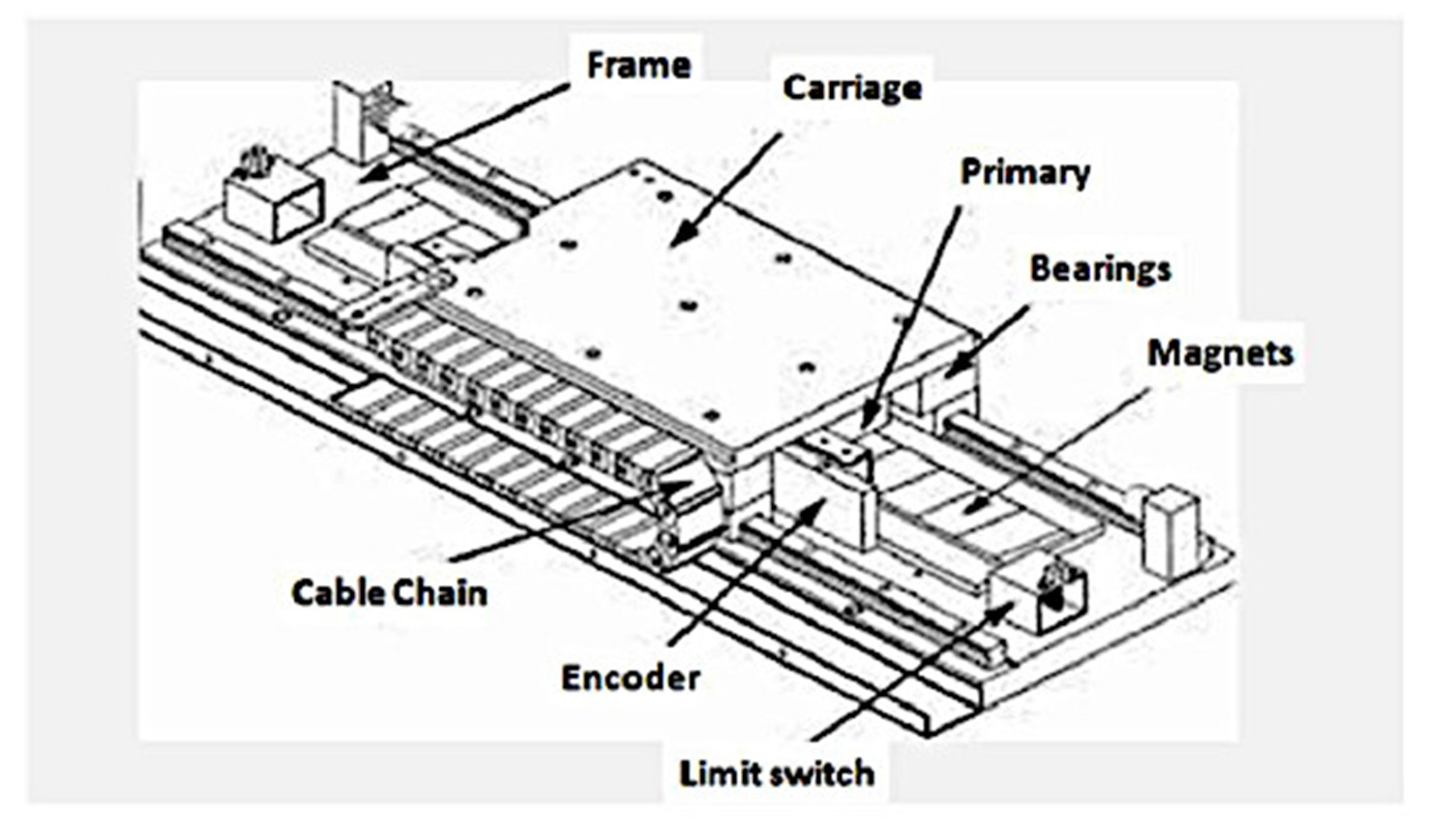
Fig 7
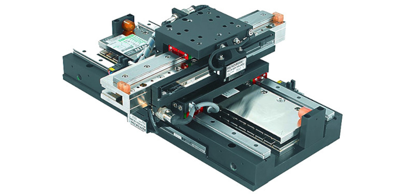
Hiwin Corporation supplies linear motors at the component level. In this case, only the linear motor and the secondary modules will be delivered. For a PMLSM motor, the secondary modules will consist of steel plates of different lengths on top of which permanent magnets will be assembled. Hiwin Corporation also supplies complete stages as shown in Fig. 7.
Such a stage includes a frame, linear bearings, the motor primary, the secondary magnets, a carriage for the customer to attach his payload, the encoder, and a cable track. A linear motor stage will be ready to start upon delivery and make life easier because the customer will not need to design and manufacture a stage, which requires expert knowledge.
Linear Motor Stage Service Life
The service life of a linear motor stage is considerably longer than a stage driven by belt, ball screw or rack and pinion. The mechanical components of indirectly driven stages are typically the first components to fail because of the friction and wear they are continuously exposed to. A linear motor stage is a direct drive with no mechanical contact or wear because the transmission medium is air. Therefore, the only components that can fail on a linear motor stage are the linear bearings or the motor itself.
The linear bearings typically have a very long service life because the radial load is very low. The service life of the motor will be dependent on the average running temperature. Figure 8 shows motor insulation life as a function of temperature. The rule is that service life will be halved for every 10 degrees Celsius that the running temperature is above the rated temperature. For example, a motor Insulation class F will run 325,000 hours at an average temperature of 120°C.
Therefore, it is foreseen that a linear motor stage will have a service life of 50+ years if the motor is selected conservatively, a service life that can never be achieved by belt, ball screw, or rack and pinion driven stages.
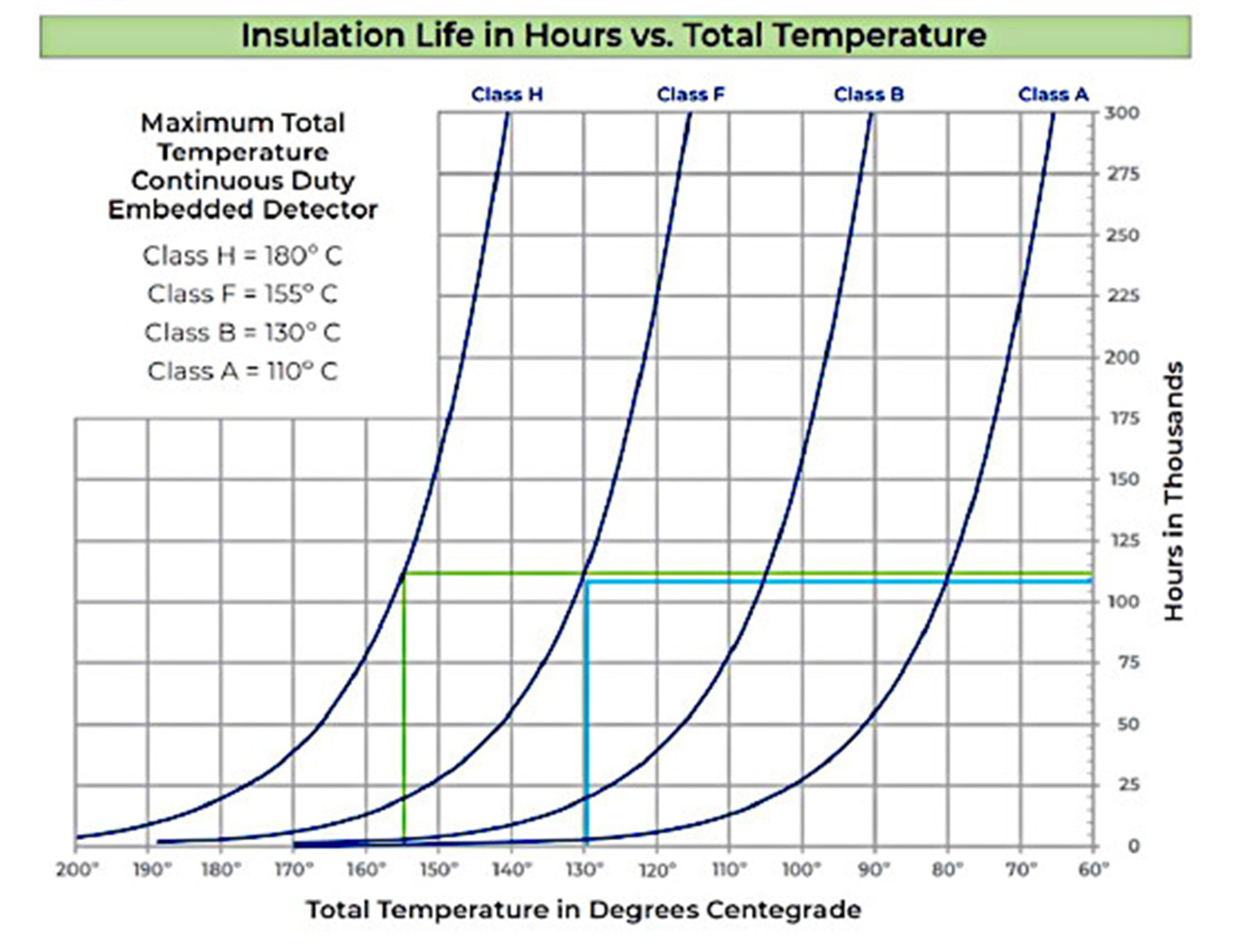
Fig 8
Applications for Linear Motors
Linear induction motors (LIM) are mostly used in applications with long travel length and where very high force is required combined with very high speeds. The reason for selecting a linear induction motor is because the cost of the secondary will be considerably lower than if using a PMLSM and at very high speed the Linear Induction motor efficiency is very high, so little power will be lost.
For example, EMALS (Electromagnetic Launch Systems), used on aircraft carriers to launch aircrafts are using linear induction motors. The first such linear motor system was installed on the USS Gerald R. Ford aircraft carrier. The motor can accelerate a 45,000 kg aircraft at 240 km/h on a 91-meter track.
Another example amusement park rides. The linear induction motors installed on some of these systems can accelerate very high payloads from 0 to 100 km/h in 3 seconds. Linear induction motor stages can also be used on RTUs, (Robot Transport Units). Most RTUs are using rack and pinion drives but a linear induction motor can offer a higher performance, lower cost, and much longer service life.
Permanent Magnet Synchronous Motors
PMLSMs will typically be used on applications with much smaller strokes, lower speeds but high to very high accuracy and intensive duty cycles. Most of these applications are found in the AOI (Automated Optical Inspection), semiconductor and laser machine industries.
The selection of linear motor driven stages, (direct drive), offers significant performance benefits over indirect drives, (stages where linear motion is obtained by converting rotary motion), for long lasting designs and are suitable for many industries.
Post time: Feb-06-2023